
Introduction
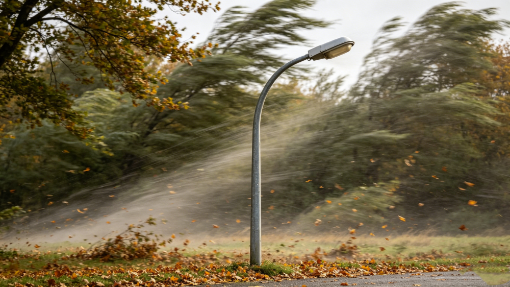
Designing a light pole to withstand wind involves more than checking a single load case or adding extra material. Wind resistance FEA helps engineers predict how the pole, base plate, welds, and openings respond to realistic pressure, vibration, and fatigue over time. This article explains how finite element analysis improves structural accuracy, supports code compliance, and reduces the risk of failure in outdoor lighting applications. It also shows where critical stress concentrations typically appear and how simulation results guide safer, more cost-effective design decisions before fabrication and installation.
Commercial Importance of Wind Resistance FEA for Lighting
The deployment of outdoor lighting infrastructure demands rigorous structural validation to mitigate the catastrophic risks associated with dynamic environmental forces. Wind resistance Finite Element Analysis (FEA) has emerged as an indispensable engineering standard for light pole design, moving the industry beyond conservative, generalized mathematical models. By simulating complex aerodynamic loads and structural responses in a virtual environment, engineers can precisely evaluate stress distribution, deformation, and fatigue limits before physical prototyping.
Incorporating FEA into the commercial development cycle directly impacts project viability, procurement strategies, and long-term maintenance budgets. For manufacturers, it streamlines material optimization; for urban planners and facility operators, it guarantees compliance with stringent municipal codes while safeguarding public infrastructure investments.
Wind Load Risk, Asset Life, and Liability
The financial implications of structural failure extend far beyond the replacement cost of a single luminaire and pole assembly. A standard 30-foot commercial light pole weighing approximately 250 pounds presents a severe liability if a localized stress fracture leads to a collapse over a pedestrian zone or active roadway. Wind resistance FEA identifies these critical failure points—often located at the base plate weld or handhole cutout—allowing engineers to reinforce the structure proactively.
Furthermore, adherence to standards such as AASHTO LTS-6 requires structures to maintain structural integrity over a 50-year design life. FEA provides the empirical data necessary to underwrite warranties, satisfy insurance prerequisites, and protect stakeholders from multi-million-dollar liability claims resulting from wind-induced infrastructure failures.
Critical Operating Contexts
Standard streetscape deployments represent only a fraction of lighting applications; critical operating contexts demand specialized wind resistance modeling. Coastal installations face extreme, sustained aerodynamic loads, frequently requiring poles certified to withstand Category 4 hurricane wind speeds exceeding 130 mph. In these environments, FEA models account for the compounding effects of wind-driven rain and prolonged gusting.
Elevated infrastructure, such as bridges and highway overpasses, introduces the phenomenon of vortex shedding, where alternating low-pressure zones create resonant vibrations. FEA enables the simulation of these complex fluid-structure interactions, ensuring that the natural frequency of the pole assembly does not synchronize with wind-induced oscillations, thereby preventing rapid fatigue failure in high-altitude or exposed topographies.
Engineering Approach to Wind Resistance FEA for Lighting
Executing a precise wind resistance FEA requires a systematic transition from CAD geometry to a highly calibrated computational mesh. The fidelity of the simulation depends entirely on the accuracy of the applied boundary conditions, material definitions, and environmental load cases. Engineers must translate meteorological data into applied mechanical forces, often utilizing coupled Computational Fluid Dynamics (CFD) to map pressure distributions across complex luminaire profiles before running the structural solver.
This methodology isolates localized stress concentrations that traditional linear calculations frequently overlook, providing a high-resolution map of the structure’s mechanical behavior under peak atmospheric stress.
Inputs, Load Cases, Boundary Conditions, and Materials
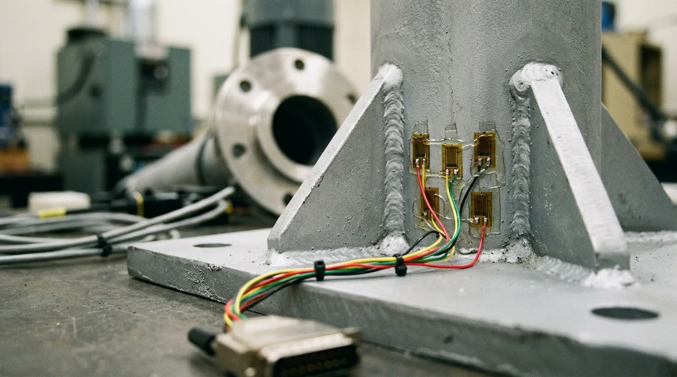
A robust FEA model begins with exact material properties. For instance, a standard carbon steel pole modeled with ASTM A500 Grade B steel requires the input of a precise yield strength of 42,000 psi and a Poisson’s ratio of 0.3. The mesh density is critical; engineers typically utilize a refined mesh of 5mm to 10mm elements around high-stress zones like base plate gussets, while allowing a coarser mesh along the uniform midsection of the shaft to optimize computational resources.
Load cases are derived from standards like ASCE 7-16, which dictate the application of wind pressure gradients that increase with elevation. Boundary conditions generally fix the base plate in all six degrees of freedom to simulate a rigid concrete foundation, while the pole shaft and luminaire attachments are subjected to dynamic pressure loads representing 3-second wind gusts.
FEA vs Hand Calculations
While manual calculations remain a baseline requirement for initial sizing, they rely on generalized shape factors and inherently conservative assumptions. FEA provides a granular, three-dimensional understanding of structural behavior that hand calculations cannot achieve.
| Metric / Feature | Traditional Hand Calculations (AASHTO) | Wind Resistance FEA |
|---|---|---|
| Drag Coefficient ($C_d$) | Generalized by basic shape (e.g., 1.2 for square) | Dynamically mapped via coupled CFD |
| Stress Resolution | Average stress across a cross-section | Pinpoints microscopic stress concentrations |
| Material Efficiency | Often results in 15-20% heavier structures | Optimizes wall thickness, reducing steel weight |
| Vibration Analysis | Limited natural frequency estimations | Comprehensive modal and harmonic response simulation |
| Complex Geometries | Struggles with asymmetrical luminaire arrays | Accurately models exact fixture and bracket EPA |
By transitioning from hand calculations to FEA, engineering teams routinely identify areas where material thickness can be reduced without compromising safety, effectively balancing cost-efficiency with uncompromising structural resilience.
Using Wind Resistance FEA for Better Lighting Decisions
The ultimate value of wind resistance FEA lies in its translation from theoretical data into actionable design and procurement decisions. By leveraging simulation results, lighting designers can confidently select pole geometries, bracket configurations, and luminaire pairings that maximize site safety and aesthetic appeal without triggering costly over-engineering.
This empirical approach transforms the specification process, allowing project teams to navigate complex environmental constraints with verifiable, data-backed confidence rather than relying on manufacturer guesswork.
Comparing Pole Geometry and Fatigue Performance
Pole geometry drastically influences aerodynamic drag and long-term fatigue resistance. FEA clearly delineates the performance disparities between cross-sectional profiles. For example, simulations demonstrate that round tapered poles exhibit a significantly lower drag coefficient ($C_d \approx 0.45$) compared to standard square poles ($C_d \approx 1.20$), resulting in drastically reduced base shear forces under identical wind loads.
Furthermore, FEA excels in fatigue performance modeling. High-mast lighting structures are frequently subjected to low-amplitude, high-frequency wind loads. By simulating up to 10 million load cycles, engineers can optimize the geometry of base gussets and weld transitions. This targeted geometric refinement often yields a 10% to 15% reduction in overall material weight while simultaneously extending the fatigue life of the asset.
Applying Results in Specification
In the specification phase, FEA results provide the definitive justification for Effective
Key Takeaways
- The most important conclusions and rationale for Wind Resistance FEA Analysis
- Specs, compliance, and risk checks worth validating before you commit
- Practical next steps and caveats readers can apply immediately
Frequently Asked Questions
Why is wind resistance FEA important for light pole design?
It shows stress, deflection, and fatigue risks before production, helping buyers avoid failures, code issues, and costly redesigns on roadway, bridge, or commercial lighting projects.
What project data is needed to start a wind resistance FEA review?
Provide pole height, arm outreach, luminaire weight and area, site wind speed, foundation details, material grade, and applicable code such as AASHTO or ASCE 7.
Can Morelux support custom pole projects with FEA-based engineering?
Yes. Morelux supports custom steel and aluminum pole projects with engineering input, technical drawings, and manufacturing coordination for infrastructure and commercial tenders.
Which areas of a light pole usually need the closest FEA attention?
Base plate welds, handhole openings, arm connections, anchor regions, and luminaire mounting points usually show the highest stress and fatigue sensitivity under wind loading.
How does FEA help sourcing professionals reduce project risk?
It improves design confidence, supports compliance checks, optimizes material use, and reduces the chance of field failure, delays, warranty claims, and expensive overdesign.