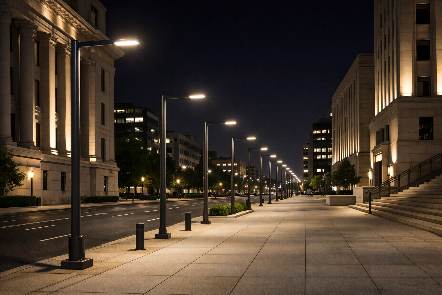
A few degrees of streetlight tilt can decide whether a roadway feels safe, efficient, and compliant—or becomes a source of glare, wasted energy, and dark gaps. Modern LED luminaires are highly directional, so the arm angle must work with the fixture optics, pole height, road geometry, and spacing plan rather than compensate for them. This guide explains how arm inclination affects luminance, uniformity, threshold increment, upward light ratio, and blind spot risk. For cities, contractors, and infrastructure buyers, getting the angle right early also reduces redesign work, avoids unnecessary poles, and supports dependable long-term lighting performance.
Why Streetlight Arm Angles Matter
The geometric orientation of a luminaire relative to the illuminated surface fundamentally dictates the efficiency and safety of a roadway lighting system. The streetlight arm angle, commonly referred to as the tilt or boom angle, alters the photometric distribution of the fixture, shifting the peak intensity of the light beam. While legacy High-Pressure Sodium (HPS) systems frequently relied on upward tilt angles between 5° and 15° to maximize forward throw, modern LED optics are highly directional and typically optimized for a 0° tilt. Deviating from the intended angle disrupts the carefully engineered light distribution pattern.
Precision in the arm angle is not merely an aesthetic concern; it is a critical engineering parameter. A variance of just 2.5° can drastically alter pavement luminance, shift the threshold increment (glare), and push a compliant lighting design into violation of local ordinances. Understanding the photometric consequences of arm inclination is the first step toward mitigating energy waste and ensuring public safety on municipal roadways.
Project risks from incorrect arm angles
Improper streetlight arm angles introduce significant liability and operational risks to infrastructure projects. If the angle is too high, a substantial percentage of the lumen output escapes the target area, leading to wasted energy and increased operating costs. For example, elevating an LED fixture from 0° to 10° can increase the Upward Light Ratio (ULR) by as much as 12%, directly contributing to sky glow and violating dark-sky compliance.
Conversely, if the arm angle is too low or negatively tilted relative to a steep road gradient, the forward throw is severely truncated. This requires municipalities to either decrease pole spacing—adding an average of $2,000 to $3,500 per additional pole installation—or accept dangerous drops in pavement luminance that increase the statistical probability of nighttime traffic accidents.
Key lighting performance terms
To accurately evaluate arm angles, lighting engineers rely on specific photometric metrics. Average Luminance (Lavg), measured in candelas per square meter (cd/m²), quantifies the light reflecting off the pavement toward the driver. Overall Uniformity (Uo) represents the ratio of minimum to average luminance, ensuring consistent visibility without harsh contrasts.
Longitudinal Uniformity (Ul) measures the ratio of minimum to maximum luminance along the centerline of a driving lane. Finally, Threshold Increment (TI) is a percentage metric used to quantify disability glare. An excessive arm angle immediately degrades TI, as the peak candela of the luminaire is lifted directly into the visual field of approaching motorists, often pushing TI well beyond the standard 10% to 15% limit.
Effects of over-illumination and blind spots
Over-illumination occurs when the tilt angle directs an excessive concentration of luminous flux directly beneath the pole (nadir) or spills light onto adjacent properties, a phenomenon known as light trespass. Exceeding a target luminance of 1.5 cd/m² on standard arterial roads (such as ME3 class) wastes wattage and creates stark visual adaptations for drivers transitioning to darker zones.
Lighting blind spots manifest when the upward angle fails to bridge the gap between widely spaced poles, causing pavement luminance to drop below the minimum threshold (e.g., 0.3 cd/m²). These dark patches obscure hazards, pedestrians, and debris. Maintaining a strictly calculated arm angle ensures the photometric footprint remains elongated and uniform, seamlessly overlapping with the distribution of the adjacent luminaire.
Variables That Determine the Correct Arm Angle
Determining the precise arm angle requires synthesizing three-dimensional site geometry with the specific optical characteristics of the selected luminaire. There is no universal tilt angle; rather, the optimal inclination is a dependent variable calculated against roadway dimensions, mounting hardware, and the targeted photometric classification.
Engineers must evaluate the interplay between the macro-level site variables—such as pole placement and road topography—and the micro-level optical engineering of the LED diode arrays. Adjusting the arm angle acts as a final tuning mechanism to align these two sets of variables, maximizing efficacy while strictly controlling backlight and glare.
Mounting height, outreach length, pole spacing, and road width
The foundational geometry of a streetlight installation dictates the required optical spread. Standard mounting heights range from 8 meters for residential streets to 12 or 15 meters for major highways. The outreach length (typically 1.0 to 2.5 meters) moves the luminaire’s optical center closer to the roadway centerline, reducing the need for aggressive upward tilt.
Pole spacing and road width establish the necessary ratio for the luminaire’s distribution. When the spacing-to-mounting-height ratio exceeds 4:1 or 5:1, engineers may be tempted to increase the arm angle to force the light to reach the midpoint between poles. However, widening the road necessitates optics with a broader lateral throw (such as Type III or Type IV distributions) rather than merely tilting a narrow optic upward.
Luminaire distribution, tilt limits, and optical design
Modern luminaires are categorized by their Backlight, Uplight, and Glare (BUG) ratings under IES standards. LED fixtures utilize secondary internal optics—specifically molded polycarbonate or acrylic lenses over individual diodes—to bend light precisely without relying on the external housing angle. Because these optics are engineered relative to a flat horizontal plane, most manufacturers mandate a 0° tilt.
If a luminaire designed for 0° is tilted to 5°, the carefully controlled peak beam angle (often engineered at 65° to 70° from nadir) shifts to 70° or 75°. This shift dramatically increases high-angle glare and bypasses the internal shielding designed to protect approaching drivers. Therefore, the luminaire’s inherent optical design is the primary constraint on permissible tilt limits.
Angle comparison criteria
When comparing potential arm angles during the design phase, engineers evaluate the trade-offs between forward throw, backlight reduction, and glare penalties. The following table illustrates the typical photometric impacts of altering the tilt angle on a standard Type III LED roadway luminaire mounted at 10 meters:
| Arm Tilt Angle | Forward Throw Multiplier | Backlight Shift | Glare (TI) Penalty |
|---|---|---|---|
| 0° (Horizontal) | 1.00x (Baseline) | Baseline | Baseline (e.g., 10%) |
| 5° Upward | 1.15x | -10% | +4% to +6% |
| 10° Upward | 1.25x | -22% | +12% to +18% |
| -5° (Downward) | 0.85x | +15% | -3% to -5% |
As demonstrated, while a 10° tilt extends the forward throw by 25%, it incurs a massive penalty in Threshold Increment, often rendering the installation non-compliant with roadway safety standards. The reduction in backlight may be beneficial for minimizing house-side trespass, but it rarely justifies the severe glare introduced to the roadway.
How to Calculate Streetlight Arm Angles
Calculating the correct streetlight arm angle is an iterative process performed within advanced photometric simulation environments, such as DIALux evo or AGi32. These software platforms utilize IES or LDT photometric files provided by the manufacturer to accurately map the three-dimensional distribution of luminous flux.
The calculation relies on the exact coordinate geometry of the roadway, including lanes, medians, sidewalks, and observer positions. By manipulating the tilt parameter within the software, designers can mathematically verify the optimal angle before any physical hardware is procured or installed.
Step-by-step calculation workflow
The calculation workflow begins by establishing the digital twin of the roadway. Engineers input the exact road width, lane count, and pavement reflectance characteristics (e.g., R3 or CIE C2 standard surfaces). Next, the luminaire’s photometric file is imported, and the mounting height, overhang, and pole spacing are locked into the model.
The arm angle is initially set to 0°. The software runs a ray-tracing calculation to generate the initial luminance and illuminance values. If the results fall short of the required uniformity or if blind spots appear, the engineer iterates the arm angle in strict 2.5° increments. Each adjustment requires a full recalculation to monitor the immediate impact on the Threshold Increment and Upward Light Ratio.
Target illuminance and uniformity requirements
The targeted metrics dictate the limits of the arm angle adjustments. For instance, under the European standard EN 13201 for an M3 motorized traffic class, the calculation must achieve an Average Luminance (Lavg) of 1.0 cd/m², an Overall Uniformity (Uo) ≥ 0.40, a Longitudinal Uniformity (Ul) ≥ 0.60, and a Threshold Increment (TI) ≤ 15%.
If tilting the arm to 5° achieves the Lavg and Ul requirements but pushes the TI to 17%, the calculation fails. The engineer must return the angle to 0° and resolve the discrepancy by altering a different variable—such as selecting an optic with a wider lateral distribution, increasing the lumen package (wattage), or reducing the pole spacing.
When field measurements should override models
While software models assume a perfectly flat and level installation environment, real-world topography often dictates that field measurements override standard calculations. Road gradients, super-elevations (banking), and sag curves alter the geometric relationship between the luminaire and the pavement.
If a roadway has a continuous uphill gradient of 6% (approximately 3.4°), a luminaire mounted perfectly level relative to gravity (0°) will effectively have a -3.4° downward tilt relative to the road surface. In such scenarios, engineers must specify an adjustable arm or slipfitter to physically tilt the luminaire +3.4° upward relative to gravity, ensuring the optical distribution strikes the pavement at the intended, mathematically modeled angle.
Compliance and Environmental Controls
Beyond photometric optimization, streetlight arm angles are strictly governed by environmental compliance frameworks and structural engineering tolerances. Regulatory bodies increasingly scrutinize public lighting to combat light pollution, protect nocturnal ecosystems, and eliminate hazardous disability glare.
Consequently, the theoretical arm angle calculated in software must survive the realities of physical installation, structural deflection, and local code enforcement. Failing to account for these compliance and environmental controls can lead to costly post-installation remediation or rejected commissioning reports.
Roadway lighting standards and glare limits
Major international frameworks severely restrict permissible arm angles. The International Dark-Sky Association (IDA) and the Illuminating Engineering Society (IES) actively promote designs that eliminate uplight. To receive the IDA Fixture Seal of Approval, a luminaire must produce an Upward Light Ratio (ULR) of exactly 0.0%. For most LED fixtures, this mandates a strict 0° horizontal mount.
The following table highlights key compliance standards and their general stance on arm angle constraints:
| Standard / Organization | Max Allowed Uplight (ULR) | Arm Angle Constraint | Primary Focus |
|---|---|---|---|
| IDA / DarkSky | 0.0% | Strictly 0° | Elimination of sky glow |
| ANSI/IES RP-8-18 | Varies by BUG rating | Limited by Glare (TI) | Roadway safety & visibility |
| EN 13201 (Europe) | Environmental Zone dependent | Limited by TI (≤10-15%) | Luminance & uniformity |
| LEED v4 (SSc8) | Zone specific (often 0%) | 0° highly recommended | Light trespass reduction |
Violating these standards by specifying excessive upward tilts can result in the loss of federal or state infrastructure funding, particularly for projects requiring strict environmental impact assessments.
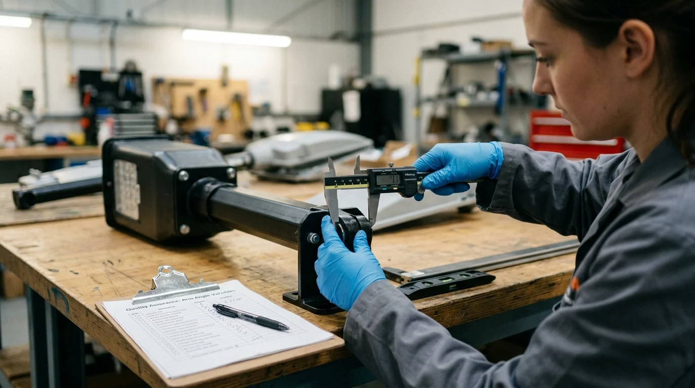
Installation tolerances and bracket deflection
The physical reality of mounting heavy equipment on extended cantilevered arms introduces structural deflection, which alters the final resting angle of the luminaire. A typical LED cobra-head luminaire weighing 10 kg to 15 kg, mounted at the end of a 2.5-meter aluminum outreach arm, will cause the bracket to sag under gravity.
Structural engineers calculate this deflection, which frequently ranges from 1.0° to 2.5° depending on the arm’s diameter, wall thickness, and material yield strength. If a 0° final angle is required for compliance, the mounting bracket may need to be manufactured with a slight initial upward camber (e.g., +1.5°) so that it deflects perfectly to horizontal (0°) once the luminaire is attached.
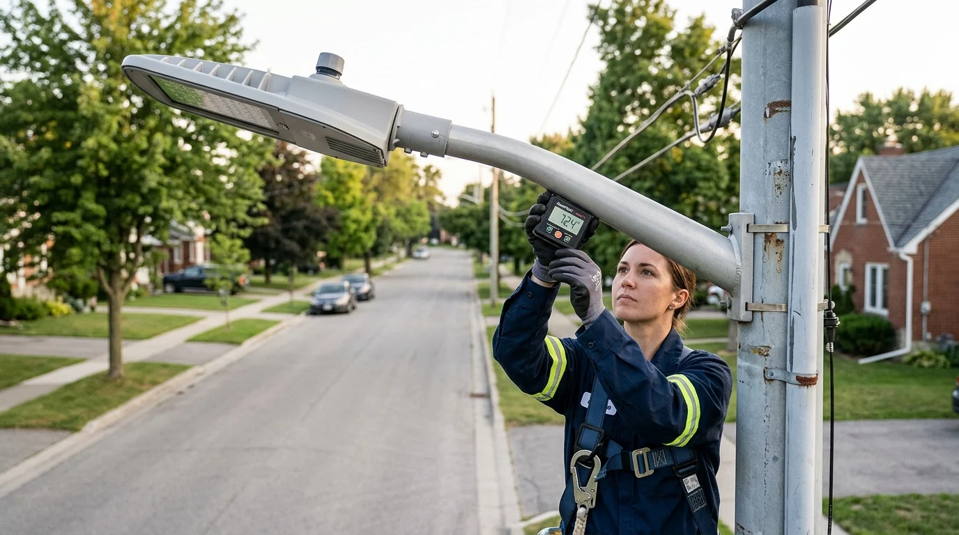
Inspection and commissioning checks
During the final phases of a lighting project, commissioning agents verify that the installed arm angles match the approved photometric models. Because the human eye cannot accurately discern a 2° or 3° deviation at a height of 10 meters, inspectors utilize digital inclinometers or laser-guided measurement tools.
Standard installation tolerances usually permit a variance of ±1.0° from the designed angle. If an inspection reveals that a luminaire is tilted at 4° instead of the specified 0°, the contractor must utilize the internal slipfitter adjustment or remount the bracket.
Choosing the Final Streetlight Arm Angle
Calculating Streetlight Arm Angles: How to Avoid Over-illumination and Lighting Blind Spots culminates in selecting the optimal final tilt. This decision dictates whether the photometric design translates effectively into physical infrastructure.
Balancing safety, energy use, and cost
The fundamental requirement of roadway lighting is to provide good visibility under night conditions, enabling motorists and pedestrians to move in a safe, coordinated manner. Achieving this requires balancing safety thresholds with energy efficiency. An excessive upward tilt wastes lumens—increasing energy costs and contributing to light pollution—while an insufficient angle creates hazardous dark zones between poles. Urban planners must calculate the exact trajectory of the luminaire to maximize the coverage area per watt without exceeding regulatory glare limits.
When to use adjustable arms or revise pole spacing
Standard fixed-angle arms are typically sufficient for straight, uniform roadways. However, complex geometries and varying street widths often require adjustable slip-fitter arms. If a calculated arm angle causes over-illumination on adjacent residential properties, engineers must re-evaluate the overarching layout.
According to the Federal Highway Administration (FHWA), standard pole spacing layout designations include one-sided, opposite, staggered, and median configurations. When a specific arm angle cannot bridge the gap between poles without causing excessive glare, modifying the FHWA spacing layout—such as switching from one-sided to staggered lighting—is a more effective structural solution than forcing an extreme fixture tilt.
Final decision framework
Municipalities enforce strict guidelines for final angle selection to maintain infrastructure uniformity. For instance, the Nashville Streets and Pathways Lighting Manual dictates specific intersection geometries, such as positioning the lighting mast arm and fixture at a 45-degree angle so the light does not shine over the mast arm, optimizing visibility where crosswalks are present.
To formalize the angle selection process, engineers should apply the following framework:
- Define the Layout: Measure the total street length and select the base FHWA spacing configuration (e.g., opposite or staggered) based on road width.
- Determine the Target Tilt: Calculate the exact angle required to meet the minimum foot-candle or luminance requirements at the furthest target point between poles.
- Verify Glare and Spill: Run photometric simulations to ensure the chosen angle does not project light beyond the public right-of-way.
- Select Hardware: Specify fixed-angle arms for standardized, linear roadway runs, reserving adjustable mounting brackets for complex intersections, steep grades, and curved road segments.
Key Takeaways
- Use the luminaire’s photometric data before changing arm angle, because most modern LED roadway fixtures are optimized for 0° tilt.
- Avoid excessive upward tilt, as moving an LED fixture from 0° to 10° can increase Upward Light Ratio by as much as 12%.
- Check glare carefully, since incorrect tilt can push Threshold Increment beyond the common 10% to 15% acceptable range.
- Prevent blind spots by matching arm angle with pole spacing, road gradient, mounting height, and the required roadway lighting class.
- Account for installation economics, because reducing pole spacing to compensate for poor angle design can add about $2,000 to $3,500 per extra pole.
- For custom roadway projects, request technical drawings and engineering review early so pole arms, brackets, and luminaires are aligned before manufacturing.
Frequently Asked Questions
What is the best streetlight arm angle for LED luminaires?
Most modern LED roadway luminaires are designed for 0° tilt because their optics already control forward throw. Always confirm with the fixture photometric file and local lighting standard before changing the arm angle.
Why can a small arm angle error cause lighting problems?
Even a 2.5° variance can shift pavement luminance, increase glare, and reduce uniformity. This may create over-illumination, blind spots, or non-compliance with municipal lighting requirements.
How does excessive upward tilt affect roadway lighting?
Too much upward tilt can waste lumens, increase sky glow, raise the Upward Light Ratio, and push glare beyond acceptable limits. A 10° LED tilt may increase ULR by up to 12%.
What happens if the streetlight arm angle is too low?
A low or negative tilt can shorten forward light throw, leaving dark gaps between poles. Projects may need closer pole spacing, which can add significant installation cost.
Which lighting metrics should engineers check when setting arm angles?
Key metrics include average luminance, overall uniformity, longitudinal uniformity, threshold increment, and upward light ratio. These show whether the design is safe, efficient, and compliant.