Lighting a mountain expressway is not just a matter of placing poles at regular intervals. Steep downgrades, tight curve radii, superelevated lanes, rock foundations, and restricted maintenance access all change how drivers perceive the road at night. A poor layout can create dark gaps, glare, confusing visual guidance, or expensive foundation conflicts. This article explains the core design logic behind safe and buildable roadway pole placement on steep curved alignments, including visibility targets, glare control, curve geometry, installation constraints, and layout selection. For infrastructure buyers and project engineers, the goal is clear: achieve compliant illumination while controlling cost, risk, and long-term maintenance demands.
Why Mountain Expressway Lighting Layout Matters
Designing a light pole layout for steep, curved mountain expressways is fundamentally different from illuminating flat, straight urban highways. Mountainous topographies introduce complex three-dimensional geometries—combining sharp horizontal curves with severe longitudinal grades—that complicate both photometric performance and structural feasibility.
Safety and visibility challenges
Safety on mountain expressways relies heavily on adequate stopping sight distance (SSD). On a 6% downgrade, a heavy vehicle’s braking distance at 80 km/h increases by over 25% compared to flat terrain. Consequently, the lighting layout must provide exceptional forward visibility without introducing disability glare. Drivers negotiating tight mountain curves must be able to visually track the road’s trajectory well in advance, making pole placement critical for optical guidance.
Cost and maintenance considerations
Beyond photometric performance, mountain environments impose severe economic and logistical constraints. Narrow rights-of-way, steep embankments, and solid rock subgrades limit where poles can be physically installed. Foundation and installation costs frequently carry a 35% to 50% premium over flat-terrain projects due to the necessity of rock excavation, specialized anchoring, and complex cable routing. Maintenance access is equally restricted, requiring layouts that minimize the need for frequent lane closures or specialized aerial lift equipment.
Key Design Terms and Parameters
A mathematically precise approach is required to adapt standard highway lighting parameters to the unique geometry of mountain expressways. Engineers must synthesize road alignment data with strict photometric criteria to ensure safety and compliance.
Road geometry and curve definitions
The primary geometric parameters dictating light pole layout include the horizontal curve radius (R), the longitudinal grade (expressed as a percentage), and the cross-slope or superelevation. On mountain routes, curve radii frequently drop below 400 meters, requiring significant deviations from standard flat-road pole spacing. Superelevation, which banks the roadway to counteract centrifugal force, alters the effective mounting height of the luminaire relative to the opposite lane, directly impacting illuminance uniformity.
Lighting performance metrics
Photometric performance is governed by several critical metrics. Average luminance (L_avg) ensures adequate overall brightness, while overall uniformity (U_o) and longitudinal uniformity (U_l) prevent alternating dark and bright patches that cause visual fatigue. Furthermore, the Threshold Increment (TI) measures the loss of visibility due to disability glare—a metric that becomes highly volatile on steep downgrades where luminaires sit lower in the driver’s forward field of view.
| Standard Class (CIE) | Avg Luminance (L_avg) | Overall Uniformity (U_o) | Longitudinal Uniformity (U_l) | Max Threshold Increment (TI) |
|---|---|---|---|---|
| M2 (High Speed/Volume) | 1.5 cd/m² | 0.40 | 0.70 | 10% |
| M3 (Medium Speed) | 1.0 cd/m² | 0.40 | 0.60 | 15% |
Comparing Light Pole Layout Options
Selecting the correct topological arrangement for light poles is the most consequential decision in mountain expressway illumination. The layout dictates not only the photometric distribution but also the optical guidance provided to the driver and the collision hazard presented by the poles themselves.
Single-side, opposite-side, and staggered layouts
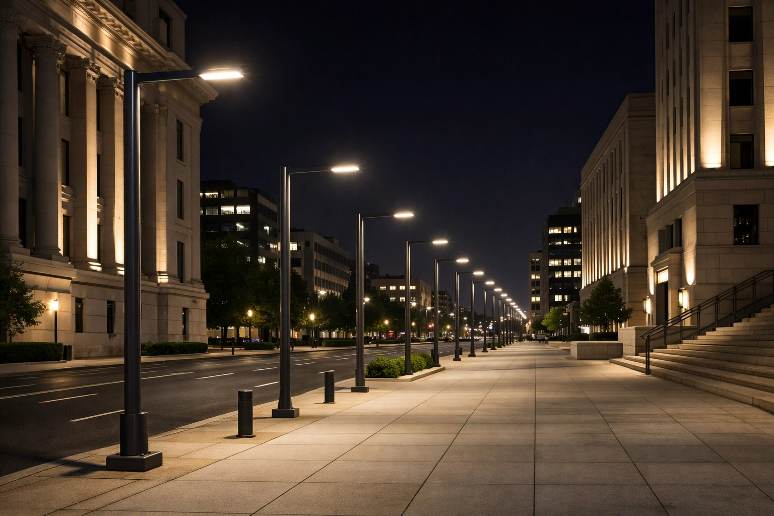
The three primary configurations are single-side, staggered, and opposite-side layouts. Staggered layouts, while efficient for straight alignments, are generally avoided on sharp mountain curves because they create confusing visual patterns (“zigzag” effects) that disrupt the driver’s perception of the road’s trajectory. Opposite-side layouts provide exceptional uniformity for wider cross-sections but require trenching and power distribution on both sides of the carriageway. Single-side layouts remain the most common choice, though the specific side chosen is dictated by the curve.
Effects of curve radius and downhill braking zones
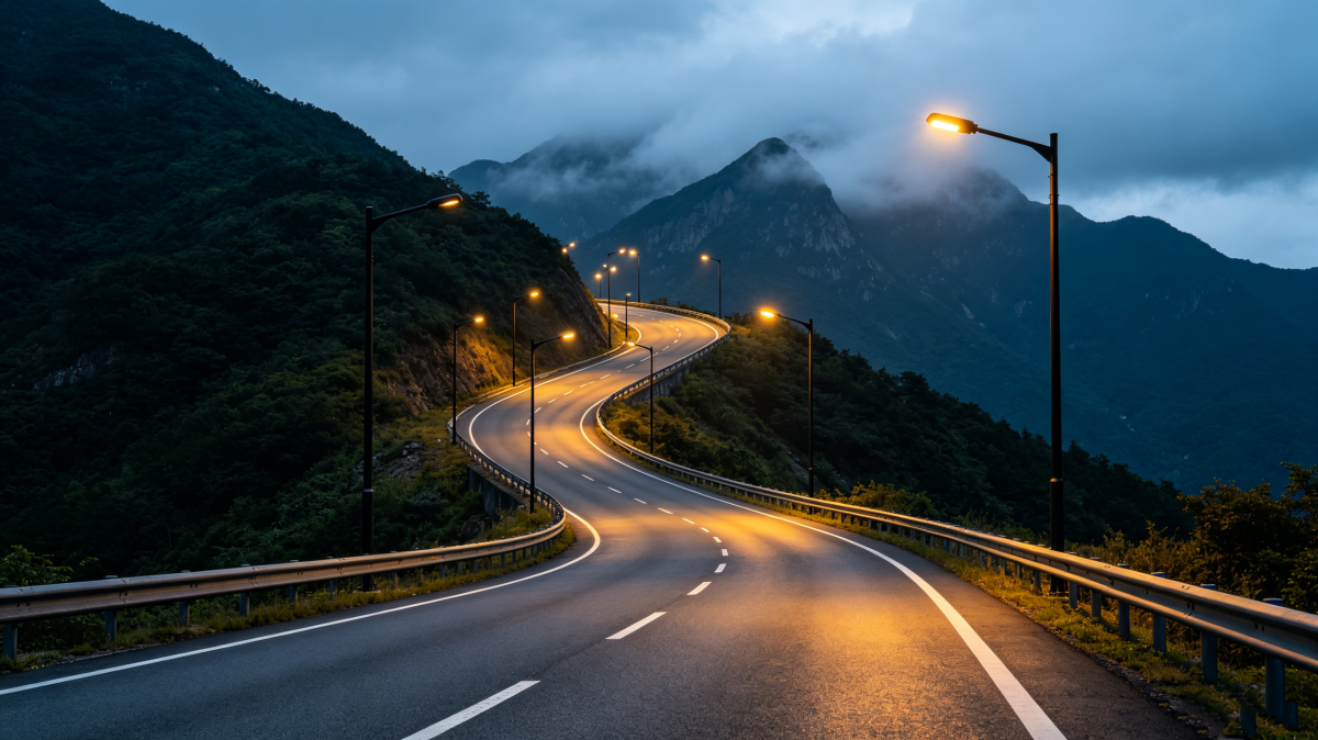
For horizontal curves with a radius (R) of less than 300 meters, single-side placement on the outside of the curve is strongly recommended. This arrangement creates a continuous line of luminaires that visually outlines the curve, providing passive optical guidance. Conversely, placing poles on the inside of a tight curve concentrates light poorly and obscures the sightline. On downhill braking zones, the spacing between poles must often be compressed by 15% to 20% to maintain longitudinal uniformity and compensate for the elongated stopping sight distances.
Safety, glare, and cost comparison
The choice of layout involves a strict balancing act between safety, glare mitigation, and infrastructure expenditure.
| Layout Configuration | Best Curve Radius Suitability | Glare Control on Downgrades | Relative Infrastructure Cost |
|---|---|---|---|
| Single-Side (Outside Curve) | R < 300m | Excellent (visual guidance) | 1.0x (Baseline) |
| Single-Side (Inside Curve) | Not Recommended | Poor (blocks sightlines) | 1.0x |
| Staggered | R > 600m (or straight) | Moderate | 1.15x |
| Opposite-Side | R < 300m (wide roads) | Excellent | 1.8x – 2.0x |
Opposite-side configurations can drive infrastructure costs up to 2.0x the baseline due to duplicated cabling, trenching, and collision barrier requirements. Furthermore, outside-curve layouts naturally position the luminaires slightly higher relative to a superelevated road surface, which inherently reduces the TI (glare) values for descending drivers.
Practical Design Workflow
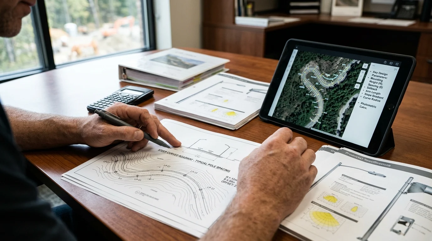
Transitioning from theoretical parameters to a fully engineered light pole layout requires a rigorous, iterative workflow. Designers must account for the three-dimensional reality of the mountain terrain, ensuring that photometric targets align with structural and environmental limitations.
From road data to preliminary pole spacing
The workflow begins by calculating a preliminary pole spacing based on straight-line formulas, utilizing the target average luminance, road width, luminaire maintenance factor, and lamp flux. However, once applied to a mountain expressway, this baseline spacing must be aggressively adjusted. A common engineering heuristic for tight mountain curves is to apply a spacing multiplier; the adjusted spacing on a curve (S_curve) is typically 0.70 to 0.85 times the straight-line spacing, ensuring that the critical longitudinal uniformity (U_l) does not degrade across the apex of the bend.
Photometric simulation and glare checks
Preliminary spacing is then imported into advanced photometric simulation software, such as DIALux or AGi32. For mountain expressways, flat-plane approximations are entirely inadequate. The simulation must incorporate the exact 3D digital elevation model (DEM) of the roadway, including all longitudinal grades and superelevations. This 3D modeling is essential for accurately calculating the Threshold Increment (TI), as a 6% downgrade will drastically alter the angle at which light enters the driver’s eyes, frequently pushing initial TI calculations past the strict 10% limit and requiring luminaire tilt adjustments.
Structural, electrical, drainage, wind, and snow factors
The workflow must simultaneously validate physical feasibility. Mountain environments subject light poles to extreme environmental stresses. Luminaires and poles must often be specified to withstand baseline wind speeds exceeding 40 m/s (144 km/h), alongside heavy asymmetric ice accumulation. Furthermore, drainage and soil stability dictate foundation design; rather than standard direct-burial methods, mountain poles frequently require engineered rock anchors driven 2 to 3 meters deep into the substrate or integration directly into precast concrete barrier walls.
Final Selection and Compliance
The ultimate light pole layout must satisfy a matrix of regulatory codes, environmental restrictions, and constructability constraints before it can be approved for installation.
Standards, agency rules, and environmental limits
Compliance begins with adhering to national and international lighting standards, such as AASHTO RP-8-18 in North America or CIE 115 globally. However, mountain expressways frequently pass through protected ecological zones or national parks, triggering strict dark-sky compliance mandates. Layouts must utilize luminaires with a Backlight, Uplight, and Glare (BUG) rating that guarantees an uplight value of U0 (0% upward emission). Additionally, a correlated color temperature (CCT) of 3000K or lower is often mandated to minimize atmospheric scattering and reduce ecological disruption to nocturnal wildlife.
Balancing cost, constructability, and performance
Balancing these compliance metrics against constructability is the final hurdle. In steep terrain where heavy crane access is impossible, the layout may need to accommodate modular poles or helicopter delivery, which strictly limits the maximum weight of the pole assemblies. High minimum order quantities (MOQs) for highly customized structural poles can inflate budgets, pushing engineers toward standardized poles spaced closer together, rather than custom-engineered poles spaced further apart.
Decision guide for the preferred layout
The preferred layout emerges from a process of elimination. Engineers must first rule out configurations that violate the 10% TI glare limit on downgrades or fail to provide outside-curve visual guidance. Next, structural and geotechnical limitations eliminate pole locations with unstable subgrades. The final layout is the configuration that achieves the target luminance and uniformity with the fewest total poles, minimizing both the initial 35-50% rock excavation premium and the long-term maintenance liabilities associated with high-altitude infrastructure.
Key Takeaways
- Account for longer stopping sight distance on steep downgrades, because a 6% grade can increase heavy-vehicle braking distance by more than 25% at 80 km/h.
- Reduce standard pole spacing on curves with radii below 400 meters to maintain optical guidance, luminance uniformity, and driver recognition of the road alignment.
- Control disability glare carefully on downgrades, where luminaires can fall lower in the driver’s forward field and cause volatile Threshold Increment values.
- Budget for mountain installation premiums of 35% to 50% due to rock excavation, specialized anchoring, difficult access, and complex cable routing.
- Select pole layouts by balancing photometric performance, roadside safety, foundation feasibility, and future maintenance access rather than using flat-road spacing rules.
- Use engineering drawings and project-specific pole customization early to coordinate mounting height, bracket reach, structural loads, coatings, and installation constraints.
Frequently Asked Questions
Why is light pole layout harder on steep curved mountain expressways?
Mountain expressways combine sharp curves, steep grades, superelevation, narrow rights-of-way, and difficult foundations. These factors affect visibility, glare, pole spacing, installation cost, and maintenance access more severely than on flat highways.
Which lighting metrics matter most for mountain expressways?
Key metrics include average luminance, overall uniformity, longitudinal uniformity, and threshold increment for glare. For high-speed routes, designs commonly target values such as 1.5 cd/m² average luminance, 0.40 overall uniformity, and TI below 10%.
How do steep downgrades affect lighting design?
On a 6% downgrade, heavy vehicles may need over 25% more braking distance at 80 km/h than on flat terrain. Lighting must therefore improve forward visibility while controlling glare in the driver’s field of view.
Why are installation costs higher in mountain areas?
Steep embankments, rock subgrades, limited access, and complex cable routing often increase foundation and installation costs by 35% to 50% compared with flat-road projects. Pole locations should be optimized early to reduce civil work.
What pole materials are suitable for mountain expressway projects?
Steel and aluminum poles can both be used, depending on wind load, corrosion exposure, weight limits, foundation design, and maintenance strategy. Morelux manufactures customized steel and aluminum roadway poles with engineering support and technical drawings.